


- Home
- Product
- About Us
- Lost Foam Casting Process
- Lost Foam Casting Video
- Success Case
- Contact Us


When buyers search for how to design airflow around coated foam pattern racks, they usually want practical guidance for a drying area that can improve coating quality, shorten drying time, reduce defects, and fit real production constraints. The top-ranking Google blog posts for similar industrial topics tend to focus on airflow principles, rack layout, drying uniformity, temperature and humidity control, and troubleshooting common drying problems. The actual purchasing group usually includes plant managers, production engineers, quality engineers, and maintenance teams. Their pain points are very specific:
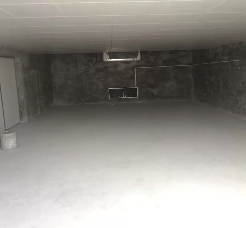
This article gives a step-by-step design guide for a drying area, including tools, operating steps, common mistakes to avoid, and practical airflow layout methods. If you are planning a new drying area or improving an existing one, Ruiou can help you build a more stable process with better drying consistency and better product quality. For reference, see our company brand Ruiou and this image: https://www.ruioulfc.com/data/watermark/20240202/65bc9e59615c3800_744.webp.
The first step is to define the drying target clearly. Before selecting fans, ducts, or rack spacing, decide what good drying means for your product. A drying area is not just about moving air. It is about controlling how coated foam patterns lose moisture or solvents without damage.
Typical targets include:
Write down the coating type, foam density, rack loading pattern, and acceptable drying time. The airflow design should support those production requirements, not force operators to work around them.
The same drying area will not work for every coated foam pattern. Lightweight foam, thick coatings, water-based coatings, and solvent-based coatings all behave differently. The airflow direction, velocity, and exhaust arrangement should be chosen based on how the coating film forms and how the foam reacts to heat and air movement.
Use these questions to guide the design:
These answers define the baseline for your airflow plan.
Start with the actual drying area dimensions. Measure the room length, width, height, door locations, exhaust positions, equipment clearance, and rack arrangement. Many airflow problems happen because the design was made from assumptions rather than actual site measurements.
Required tools:
Mark the position of each coated foam pattern rack. Note the aisle width, stack height, and any obstructions such as columns, panels, or conveyors.
Once the layout is clear, map the airflow path. Good drying area design usually follows a controlled route: clean supply air enters, travels across the racks, picks up moisture or solvent vapors, and exits through a planned exhaust path. If the air path is too short or blocked, some zones dry too fast while others stay wet.
When mapping the route, check:
The goal is to avoid short-circuit airflow, where air goes directly from inlet to outlet without properly contacting the coated parts.
Rack placement is one of the most important factors in a drying area. Even strong fans cannot fix poor rack layout. The racks should be arranged so that air can pass through and around the coated foam pattern surface with minimal blockage.
Follow this step-by-step layout method:
Uniform spacing helps air distribute more evenly. Tight corners and wall-adjacent positions often become low-flow zones, which slow drying and create quality differences.
The internal design of the rack matters as much as the room design. If the coated foam pattern is packed too closely, air cannot reach all surfaces. If the rack structure is too solid, it blocks airflow and creates shadow areas.
Important rack design points:
Ruiou often recommends reviewing rack geometry together with the drying area design, because the best airflow plan can fail if the rack structure creates blockage.
Airflow direction controls evaporation rate and drying balance. In many drying areas, the most common options are horizontal flow, vertical flow, or a combination of both. The best choice depends on coating sensitivity and rack orientation.
Use this practical guide:
A common mistake is using a stronger fan to solve a uniformity problem. In reality, airflow direction and distribution are often more important than raw speed.
Too much velocity can create defects such as rippling, edge drying, or skin formation before the inside is ready. Too little velocity can slow evaporation and leave the coating tacky. The airflow design should keep a stable speed across the product zone, not just at the fan outlet.
Practical steps:
Use real product response, not only sensor data, to validate the airflow setting.
Airflow alone cannot solve drying issues if temperature and humidity are unstable. In a drying area, environmental control directly affects evaporation rate, surface quality, and batch consistency. If humidity is too high, drying slows down. If temperature is too high, foam or coating may be damaged.
Track these key factors:
A stable drying area should keep these conditions within a defined range during the full drying cycle.
Design the control sequence so the drying area reacts consistently to changing load conditions. For example, when a full rack batch enters, the system may need a staged temperature ramp and controlled exhaust adjustment. When the load is lighter, the system may need less aggressive airflow.
Simple control sequence example:
This controlled sequence prevents sudden environmental swings and improves repeatability.
Designing airflow is only half the job. Verifying it is equally important. A drying area should be tested with simple and reliable tools before full production starts. These tools help confirm whether the air actually reaches every rack level and product zone.
Recommended tools:
Use these tools to compare airflow before and after layout adjustments.
One common mistake is measuring airflow at the fan outlet and assuming the whole drying area performs the same way. Instead, test many points across the room and on different rack levels. This reveals hidden weak spots.
Test plan example:
When the data shows large variation, adjust baffles, rack positions, or exhaust balance until the readings become more even.
Poor loading is one of the most frequent causes of drying problems. If operators overload a rack or place parts too close together, the airflow design loses effectiveness. This creates uneven evaporation, sticky areas, and longer drying time.
Common loading mistakes:
Train operators to follow a standard loading pattern every time.
Even a well-designed drying area can fail if filters, fans, or ducts are dirty or partially blocked. Maintenance issues reduce airflow and create hidden variability.
Common maintenance-related mistakes:
Schedule regular inspection so the airflow remains consistent over time.
Changing fan speed, temperature, or rack position without measurement often makes the problem worse. The right approach is to change one variable at a time and record the result. This is especially important in a drying area where multiple factors interact.
Best practice steps:
Before redesigning the entire drying area, test the airflow concept in one controlled section. A pilot zone lets you validate rack layout, air direction, and drying performance with limited risk. This is especially useful when production volume is high and downtime is costly.
Pilot implementation steps:
If the pilot results are good, expand the same design logic to the full drying area.
Once the airflow design works, write a standard operating procedure so every shift uses the same method. This keeps the drying area consistent and reduces operator-to-operator variation.
The SOP should include:
A standard method protects the process and makes future troubleshooting much easier.
Before releasing the drying area for full production, review the design from three angles: airflow performance, operational ease, and finished product quality. A design that looks good on paper but is hard for operators to use will not stay effective.
Final checklist:
Airflow design is not a one-time task. Seasonal changes, product changes, and production volume changes can all affect performance. Review the drying area regularly and update the airflow settings if conditions change.
Ruiou supports customers who want to improve drying area consistency over time, especially when coated foam pattern racks need stable airflow, lower defect rates, and repeatable output.
In summary, designing airflow around coated foam pattern racks starts with understanding the drying area, then measuring the layout, arranging racks correctly, selecting the proper airflow pattern, controlling temperature and humidity, verifying performance with the right tools, and avoiding common mistakes. A structured step-by-step method gives better results than trial and error, and it helps production teams create a more reliable drying area with better quality and faster turnaround.
For more practical industrial drying area solutions, Ruiou can support your planning, layout optimization, and performance verification needs.
Previous: None




Copyright © Hebei Ruiou Intelligent Equipment Co., LTD. All Rights Reserved. | Sitemap | Powered by